


Understanding the Working Principle and Common Issues of Diaphragm Carburetors
Introduction
Diaphragm carburetors are essential components in various machines, serving a crucial role in fuel delivery and combustion processes. In this blog post, we will explore the structure, functionality, and working principles of diaphragm carburetors, shedding light on their common applications and potential issues.
Structure and Applications
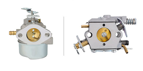
Diaphragm carburetors, known for their versatility and efficiency, consist of key components such as the intake port, negative pressure port, and fuel inlet. These carburetors find widespread use in small engines, motorcycles, chainsaws, and other machines requiring precise fuel-air mixture control. The intricate design of these carburetors ensures optimal performance in diverse operating conditions.

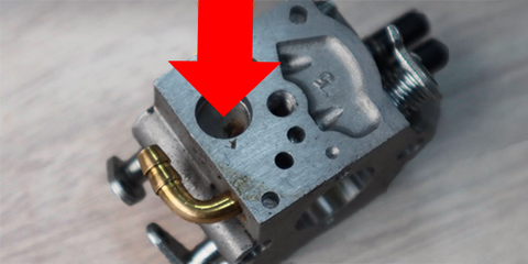
Intake Port: This is where air enters the carburetor.
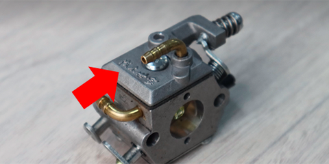
Negative Pressure Port: Connected to the piston, it plays a crucial role in creating the necessary vacuum for fuel delivery. The negative pressure port is as below.

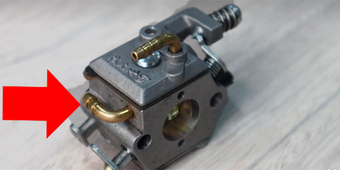
Fuel Inlet: This is the entry point for fuel into the carburetor. Picture below.
Functionality and Working Principles:
Diaphragm carburetors integrate the functions of both a fuel pump and a carburetor, simplifying the fuel delivery process. Understanding their working principles involves examining the diaphragm's behavior as the piston moves through different positions.
Upward Movement of Piston: As the piston moves upward, the negative pressure tube generates pressure, transferring it to the diaphragm. This upward motion creates a sealed area within the diaphragm, inducing a vacuum at the fuel inlet. Through a unidirectional valve, fuel is drawn into the recessed area covered by the diaphragm.
Downward Movement of Piston: When the piston moves downward, positive pressure is transmitted through the negative pressure tube, causing the diaphragm to move downward. This action compresses the previously drawn fuel, pushing it into the carburetor's metering chamber for precise fuel measurement.

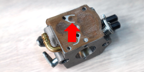
one-way valve on diaphragm carburetor
Metering and Combustion:
The metering chamber, equipped with a diaphragm featuring a metal protrusion, plays a crucial role in regulating fuel flow. As the piston moves upward, the diaphragm lifts the metal protrusion or presses down on a metal needle, allowing gasoline from the upper chamber to flow through holes. The mixture then passes through the idle screw (L screw) and high-speed screw (H screw), reaching the combustion chamber after atomization.
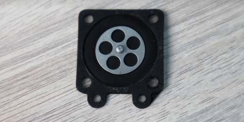
metal protrusion
Diaphragm carburetors, with their ingenious design and dual functionality, contribute significantly to the efficiency of various machines. By comprehending their structure and working principles, users can better appreciate the importance of these components. However, like any mechanical system, diaphragm carburetors are susceptible to issues such as clogging or wear over time, emphasizing the need for regular maintenance to ensure optimal performance.
Common Problems and Troubleshooting of Diaphragm Carburetors:
Stiff Diaphragm:
Symptoms: Difficulty in starting the engine, poor acceleration, or irregular idling.
Troubleshooting: Check for dirt, debris, or varnish accumulation on the diaphragm. Clean the diaphragm and surrounding components, ensuring smooth movement. If the diaphragm is damaged or worn, replace it with a new one.
You could find the new diaphragm for your carburetor here
Blocked Holes:
Symptoms: Engine stalling, uneven performance, or loss of power.
Troubleshooting: Inspect the carburetor for clogged or obstructed fuel and air passages. Clean the carburetor thoroughly, paying special attention to tiny holes and channels. Use carburetor cleaner and compressed air to remove any debris. Regularly clean and maintain the carburetor to prevent future blockages.
Damaged Non-Return Valve:
Symptoms: Fuel leakage, poor fuel delivery, or flooding.
Troubleshooting: Examine the non-return valve for wear, tears, or damage. If faulty, replace the valve with a new one. Ensure that the valve is seated correctly and functions properly to prevent fuel from flowing back into the carburetor when it should be closed.
Idle Issues - Incorrect Mixture:
Symptoms: Rough idling, stalling at low speeds, or difficulty maintaining a stable idle.
Troubleshooting: Adjust the idle mixture screws (L screw) and (H screw) to achieve the correct air-fuel mixture. If the idle remains unstable, clean the carburetor, paying attention to the idle circuit. Check for vacuum leaks, gaskets, or seals that may be compromised, affecting the mixture.
Fuel Starvation or Flooding:
Symptoms: Engine runs lean (starvation) or rich (flooding), resulting in poor performance.
Troubleshooting: Inspect the fuel inlet and needle valve for proper functioning. Adjust the float level if necessary to regulate fuel supply. Ensure that the fuel pump, if present, is delivering fuel consistently. If flooding persists, check for a stuck needle valve and correct the issue.
Irregular Combustion:
Symptoms: Backfiring, misfires, or erratic engine behavior.
Troubleshooting: Verify that the diaphragm and associated components are in good condition. Check for air leaks around the carburetor and intake manifold. Adjust the high-speed screw (H screw) for optimal fuel mixture at higher RPMs. If issues persist, consult the manufacturer's guidelines for further diagnostics.
Regular maintenance, inspection, and prompt troubleshooting can help address these common issues with diaphragm carburetors, ensuring reliable performance and extending the lifespan of the engine.


6 Comments
Thanks a lot! I appreciate it!
adelaide casino pokies online https://combatcasino.info/real-money-online-casino-texas/ indiana online casino apps
Kudos! Lots of write ups.
new online casino slot games https://combatcasino.info/real-money-online-casino-tennessee/ most popular online casino slots
Incredible quite a lot of helpful info!
golden toad online casino https://combatcasino.info/ volcano online casino
You reported this exceptionally well!
ireland online casino https://casinosonlinenew.com/mbl-betting/ online casinos like stake.us
Balancing procedures for equipment maintenance with Balanset-1AWatch YouTube Short
The process of balancing a rotor using the Balanset-1A device by Vibromera includes several key steps, from equipment preparation to the installation of correction weights.
Equipment Preparation:
1. Place vibration sensors perpendicular to the rotor’s axis of rotation.
2. Attach the laser tachometer on a magnetic stand, directing it towards the reflective tape on the pulley.
3. Connect the sensors to the device and link the device to a laptop via USB.
4. Launch the Balanset software, selecting the balancing mode in two planes.
Initial Vibration Measurement:
Prior to balancing, suspend a test weight and record its weight and installation radius.
Start the rotor and measure the initial vibration level to determine the amplitude and phase of the initial imbalance.
Balancing in the First Plane:
Place the test weight in the first balancing plane corresponding to the location of the first sensor.
Run the rotor to measure the vibration level. Ensure a 20% change in amplitude or phase, indicating partial correction of the imbalance.
Balancing in the Second Plane:
Transfer the test weight to the second plane (where the second sensor is located), restart the rotor, and conduct measurements to calculate the precise position and weight of the correction weights.
Imbalance Correction:
Based on the data collected, the Balanset program will suggest correction weights and their installation angles for both planes.
Prepare the correction weights as per the program’s recommendations and install them at the required angles in the rotor’s direction of rotation from the initial test weight position.
Verification and Completion of Balancing:
Run the rotor for a final balance check. If the vibration has reduced to an acceptable level, the process is completed. If further correction is needed, the program will indicate where and how much additional weight to install.
Device Components:
Vibration transducers – 2 pcs. Phase angle sensor (laser tachometer) – 1 pc. Measuring unit (Balanset device) – 1 pc. Magnetic stand – 1 pc. Electronic scales – 1 pc. Transportation case – 1 pc. Software on a flash drive – 1 pc.Price: 1751 euros. Balancing of rotors in one or two correction planes.
Balancing in One Plane (“Static”):
Typically done for narrow disc-shaped rotors without significant axial runout.
Examples include grinding wheels, pulleys, flywheels, gears, clamping chucks, fans, etc.
Balancing in Two Planes (“Dynamic”):
Performed for long two-support rotors like motor and generator rotors, compressor and pump rotors, turbine and fan impellers, spindles, etc.
Ensure mechanisms are in good condition, securely mounted, and clean before balancing.
Pre-Balancing Recommendations:
Check for significant static imbalance before using the device. For horizontally positioned rotors, manually rotate the rotor by 90 degrees. If it remains unbalanced, add a balancing weight at the top.
Recommendation:
Verify vibration levels before balancing to ensure effective correction and machinery health.
Information:[/b]For more information about our Balanset balancing devices and other products, please visit our website: https://vibromera.eu.
Subscribe to our YouTube channel, where you will find instructional videos and examples of completed work: https://www.youtube.com/@vibromera.
Stay updated with our latest news and promotions on Instagram, where we also showcase examples of our work: https://www.instagram.com/vibromera_ou/.
Buy Balanset-1A on Amazon
Balanset-1A OEM on Etsy